Two and Three-Phase Separators
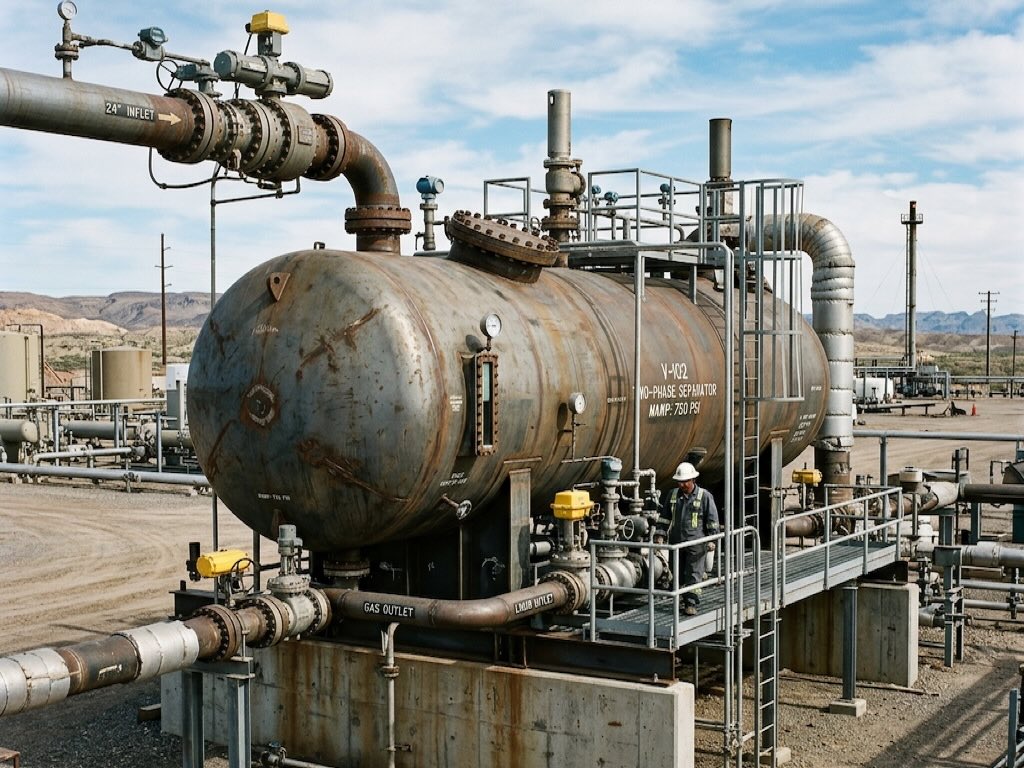
In the upstream and midstream sectors of the Oil and Gas industry, raw fluid extracted directly from a wellhead is never a pure product. It arrives at the surface as a turbulent, highly pressurized mixture of crude oil, natural gas, salt water, and solid particulate matter. Phase separators are massive pressure vessels purposefully engineered through advanced design and consultancy to physically untangle and isolate this chaotic multiphase mixture into distinct, recoverable process streams.
The Science of Gravity Separation
Almost all industrial separators rely on the fundamental principle of gravity settling, governed by Stokes’ Law. Because liquids are substantially denser than gases, and water is noticeably denser than crude oil, simply allowing the turbulent wellstream to drastically slow down allows gravity to naturally pull the heavier elements to the bottom, while the lighter gases naturally percolate upwards.
To facilitate this, separators are physically sized via rigorous process engineering formulas to guarantee adequate “retention time,” deliberately holding the fluid undisturbed inside the tank long enough for complete gravitational segregation to occur.
Comparing Two-Phase and Three-Phase Operation
| Type of Separator | Function & End Products | Ideal Industry Use-Case |
|---|---|---|
| Two-Phase Separator | Splits the inlet stream strictly into two isolated phases: liquid (an oil/water emulsion) and gas. | Dry gas fields, initial high-pressure flare knock-out drums. |
| Three-Phase Separator | Splits the stream into three distinct phases: gaseous vapor, purified light hydrocarbon oil, and heavy “free” water. | Wet oil wells, early production facilities (EPFs), downstream water desalinization units. |
Internal Vessel Architecture
While the empty shell of a pressure vessel provides the volume for retention time, modern phase separators require highly engineered internal hardware to accelerate the physical separation process and prevent fluid carry-over limitations.
- Inlet Diverter: The raw feed enters at high velocity. It instantly slams into an impingement baffle or cyclone diverter. This violently dissipates the incoming momentum, flashing off large volumes of gas instantly.
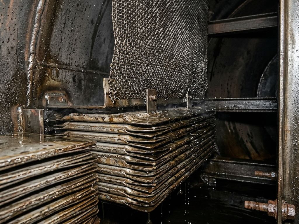
- Coalescing Plates: Used extensively in three-phase tanks, these tightly stacked plates force microscopic water droplets trapped inside the oil to repeatedly collide. They coalesce into massive drops that finally become heavy enough to sink into the water zone.
- Mist Extractors: A mesh pad or vane pack situated at the very top of the vessel near the gas exit nozzle. It physically strips microscopic liquid aerosols still trapped inside the rising gas stream, ensuring only bone-dry gas is routed toward expensive downstream compressors.
Note on Skidded Modules: Phase separators are exceptionally heavy vessels that require extensive supporting valving (level controllers, dump valves, PRVs). Due to their complexity, they are almost universally designed and transported as complete 3D modular skid packages directly from the fabrication yard.
Vessel Orientation: Horizontal vs Vertical
Phase separators are generally manufactured as either vertical cylinders or horizontal torpedoes. A horizontal configuration provides drastically more interfacial surface area between the liquid layers, making them far superior for high-volume three-phase liquid/liquid extraction. A vertical configuration possesses a much smaller footprint and handles large quantities of mud or sand with less risk of permanent internal clogging.