Heat Exchanger Simulator & Calculator
Hot Side
Cold Side
Fluid Simulation
Temperature Profile
Model Sizing Table
| Model | Heat Area (m²) | Plate Qty | Duty Margin (%) | DN | Hot ΔP (kPa) | Cold ΔP (kPa) |
|---|---|---|---|---|---|---|
| No models calculated yet. | ||||||
Results & Recommendations
Calculated Parameters
Overall Heat Transfer Coeff. (W/m²K): -
LMTD (°C): -
Heat Transfer Area (m²): -
Material Recommendation
-
-
Hydraulic & Design Margin
Expand Plate Geometry panel below to calculate pressure drop and duty margin.
Balance & Auto-Corrections
Balance Status: -
Real Heat Load (kW): -
Design Heat Load (kW): -
Hot ΔT (°C): -
Cold ΔT (°C): -
Updated Values
Auto-Change Notes
Select Heat Exchanger Type


▶ Plate Geometry (for Hydraulic Calculation — click to expand)
Friction factor: Martin (1996) — Shah & Sekulić (2003, §7). Port loss: K=1.5·ρu²/2. Duty margin: area ratio method (Hewitt et al., 1994).
Contact Us With This Selection
Frequently Asked Questions
Q: How do I size a plate heat exchanger?
Calculate thermal duty (Q = ṁ × Cp × ΔT), determine LMTD for your temperature profile, estimate the U-value based on your fluids, then use A = Q / (U × LMTD) to find the required heat transfer area. Add 10–25% fouling margin and verify pressure drop stays within limits. Use our free calculator to verify your results.
Q: What formula is used for heat exchanger sizing?
The primary formula is A = Q / (U × LMTD) where A is the required heat transfer area (m²), Q is the thermal duty (W), U is the overall heat transfer coefficient (W/m²·K), and LMTD is the log mean temperature difference (°C). For the thermal duty: Q = ṁ × Cp × ΔT.
Q: What is LMTD and why is it important for sizing?
LMTD (Log Mean Temperature Difference) is the effective average temperature difference between hot and cold fluids across the heat exchanger. It accounts for the fact that the temperature difference changes along the length of the exchanger. The formula is: LMTD = (ΔT₁ − ΔT₂) / ln(ΔT₁ / ΔT₂). A higher LMTD means less heat transfer area is needed.
Q: What is a typical U-value for a plate heat exchanger?
Typical U-values for plate heat exchangers: water-to-water = 3,000–5,000 W/m²·K, water-to-glycol = 2,000–4,000 W/m²·K, steam-to-water = 3,500–5,500 W/m²·K, oil-to-water = 500–1,500 W/m²·K. These are 2–5× higher than shell & tube due to turbulent flow in corrugated plates. See our U-value guide for details.
Q: How much fouling margin should I add?
Add 10–15% extra area for clean fluids (treated water, glycol), 15–20% for moderately fouling fluids (cooling tower water, soft water), and 20–25% for heavily fouling fluids (untreated water, oil). Over-sizing beyond 25% is generally not recommended as it reduces fluid velocity and can actually increase fouling.
Request a Quote for OEM Equivalent Parts – GPHE Spare Parts
Select your specifications step by step and we’ll get back to you with a competitive quotation.
Select Brand
What Do You Need?
Select the type of spare parts required.
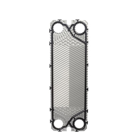 Plates Only
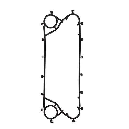 Gaskets Only
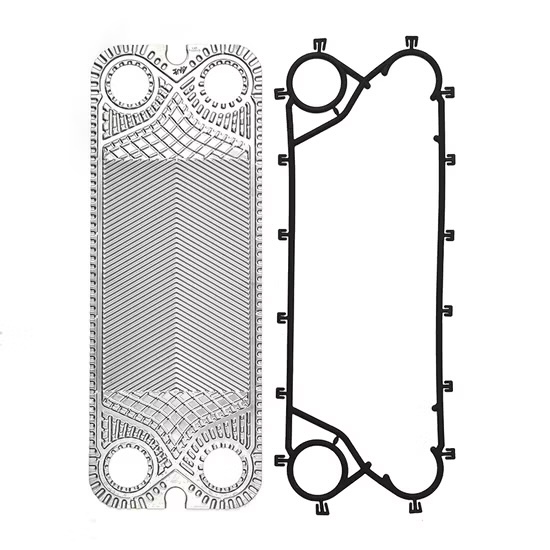 Plates & Gaskets
Specifications
Enter quantities and select material.
Plates
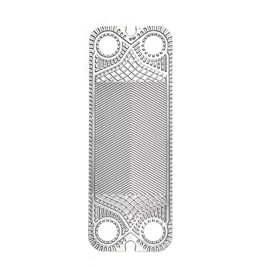 Flow Plate
 End Plate
Plate Material
Gaskets
Flow Gasket
 End Gasket
Gasket Material
Your Details
We'll contact you with a quotation. Fields marked * are required.
Review Your Selection ▼
Inquiry Sent!
Thank you. We will review your inquiry and get back to you shortly.