Is the Pressure Drop Issue Real? Let’s Solve the Puzzle!
Understanding the Setup
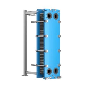
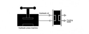
In a standard water system, water is pumped throughout a building from a basement pump using typical fittings. The pipework is DN150, with a flow rate of about 18 liters per second, resulting in a pipe velocity of approximately 1 m/s. A gasketed plate and frame heat exchanger (PHE), also located in the basement, is connected on the suction side of the pump with minimal pipework. The pipe diameter reduces from DN150 to DN65 at the PHE inlet and outlet, resulting in a velocity of around 5.4 m/s. An over-pressurization unit adds an extra pressure of 1 bar into the water circuit.
Sequence of Events
When the pump is activated, the power reading exceeds the expected value shown on the pump curve.
Investigation Process
To investigate, check the pressure drop across the different components in the pipework, starting with the PHE due to its proximity to the pump and expected high pressure drop. Measure the pressure at both the PHE inlet and outlet. The pressure difference observed is greater than what the supplier’s data sheet indicates.
Unraveling the Mystery
The investigation shows that the pump is drawing more power than anticipated because the higher pressure drop at the PHE was not considered during pump sizing. But is this the whole story?
Considering Alternative Explanations
Could the pump itself be the issue? One possibility is that the pump is slightly undersized for the required duty. This could happen if the pump curve is inaccurate or if the motor horsepower is not as advertised. A struggling centrifugal pump might experience cavitation; however, the 1 bar overpressure helps keep air from separating from the water, minimizing cavitation at the pump impeller and allowing it to operate effectively.
The PHE on the pump’s suction side has the highest pressure drop, causing significant flow resistance. As the impeller draws water, a slight negative pressure builds at the PHE outlet. To balance this, a positive pressure forms at the PHE inlet. Therefore, pressure readings taken between the PHE inlet and outlet may be exaggerated, implying that the pressure loss across the PHE exceeds the manufacturer’s stated values.
Conclusion
Adding overpressure to a water system changes its dynamics, effectively increasing the “head” pressure that must be considered when selecting the right pump motor. This overpressure reduces cavitation, but if the motor is not powerful enough, a negative pressure can develop on the suction side, leading to a positive pressure on the pump’s discharge side.
A Quick Math Overview:
- The system loss adds 2.5 meters of head to the pump.
- The pressure drop across the PHE is equivalent to 7 meters of head.
- Total Head: 9.5 meters at a flow rate of 18 liters/second.
- Overpressure introduced by the pressurization unit = 10 meters.
Required Motor Horsepower:
- Without overpressure: 18×9.595=1.8 horsepower\frac{18 \times 9.5}{95} = 1.8 \text{ horsepower}9518×9.5=1.8 horsepower (95 is a constant used for horsepower calculation).
- With Overpressure: Total loss calculation: Total Loss=(OP+SL)×(OP+SL)SL\text{Total Loss} = \frac{(OP + SL) \times \sqrt{(OP + SL)}}{\sqrt{SL}}Total Loss=SL(OP+SL)×(OP+SL) Where:
- OP = overpressure
- SL = system loss
Substituting (SL = 9.5) and (OP = 10): Total Loss = 27.9 meters should be the basis for motor power requirements, indicating a necessary horsepower closer to 6 HP, compared to the 2 HP derived without considering overpressure.
Final Question
Does the added overpressure hide an undersized pump motor, or is the PHE’s pressure reading from the manufacturer inaccurate?
