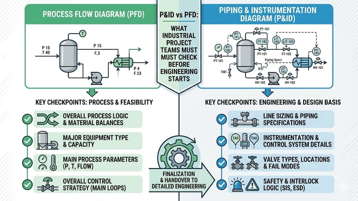
P&ID vs PFD: What Industrial Project Teams Must Check Before Engineering Starts
A PFD shows how the process works at a high level, while a P&ID shows how the plant will be controlled, operated, isolated, protected, and maintained. Industrial project teams should check both documents before detailed engineering, procurement, and construction begin.
In industrial projects, two drawings often decide whether the engineering phase starts clearly or becomes full of revisions: the Process Flow Diagram and the Piping and Instrumentation Diagram. They are connected, but they do not serve the same purpose.
A PFD helps process engineers explain the main process route, equipment, flow rates, operating conditions, heat and material balance, and utility requirements. A P&ID goes deeper. It shows piping, valves, instruments, control loops, alarms, interlocks, drains, vents, bypasses, safety devices, and operating details.
For Oil & Gas facilities, petrochemical plants, HVAC systems, food and beverage factories, pharmaceutical plants, power generation units, mining plants, steel mills, marine systems, ethanol plants, and paper mills, the difference between PFD and P&ID is not academic. It affects equipment selection, heat exchanger sizing, piping design, procurement packages, HAZOP preparation, vendor document review, commissioning, and long-term maintenance.
This article explains the difference between P&ID and PFD and, more importantly, what industrial project teams must check before engineering starts.
Simple Definition: What Is a PFD?
A PFD, or Process Flow Diagram, is a high-level engineering drawing that shows the main process equipment, process streams, flow direction, heat and material balance, major control points, and utility connections. It explains how the process works before detailed piping and instrumentation are added.
In practical engineering, the PFD is usually prepared after the design basis and process simulation are developed. It helps the process team confirm equipment duties, stream conditions, operating cases, heating and cooling loads, and the general process route.
Simple Definition: What Is a P&ID?
A P&ID, or Piping and Instrumentation Diagram, is a detailed engineering drawing that shows piping, valves, instruments, control loops, alarms, safety devices, drains, vents, bypass lines, equipment connections, and operating details. It is one of the most important documents for detailed engineering, procurement, construction, commissioning, operation, and maintenance.
For industrial projects, the P&ID is where process engineering connects with mechanical design, piping design, instrumentation, electrical interfaces, safety studies, procurement, and plant operation.
Quick Answer: P&ID vs PFD
A PFD explains the process flow and main operating conditions, while a P&ID explains the detailed piping, valves, instruments, controls, safety devices, and operating connections. A project should not move into detailed engineering until both drawings are consistent with the design basis.
The PFD answers “what is the process and what are the main conditions?” The P&ID answers “how will the process be built, controlled, isolated, protected, drained, vented, operated, and maintained?”
Before engineering starts, project teams should confirm that the PFD, P&ID, equipment list, line list, instrument list, heat and material balance, process simulation, and procurement datasheets do not contradict each other.
PFD vs P&ID Comparison Table
| Item | PFD | P&ID |
|---|---|---|
| Main purpose | Shows how the process works | Shows how the plant is piped, controlled, isolated, and operated |
| Level of detail | High-level process information | Detailed engineering information |
| Main users | Process engineers, project engineers, client technical teams | Process, piping, mechanical, instrument, electrical, safety, procurement, operation, and maintenance teams |
| Typical content | Main equipment, process streams, flow direction, temperatures, pressures, flow rates, utilities | Piping, valves, instruments, control loops, alarms, interlocks, drains, vents, relief devices, line numbers |
| Used for | Process understanding, simulation review, heat and material balance, early equipment sizing | Detailed engineering, procurement, HAZOP, construction, commissioning, operation, maintenance |
| Procurement impact | Defines main process duties and equipment requirements | Defines detailed connections, valves, instruments, safety devices, and vendor interfaces |
Why PFD and P&ID Checks Matter Before Engineering Starts
Many engineering problems begin when a team starts detailed design before the PFD and P&ID are aligned. A heat exchanger may be sized from one duty while the P&ID shows a bypass or operating condition that changes the real flow. A pump may be selected before the suction arrangement is checked. A tank may be purchased before venting, overflow, drain, and instrumentation are finalized. A pressure vessel may be quoted before the design pressure, relief philosophy, and nozzle arrangement are agreed.
Industry practice is to review PFDs and P&IDs together with the design basis, process simulation, equipment datasheets, and procurement requirements. Heating Formula supports this through PFD and smart P&ID engineering services, process design and simulation, static equipment design, and procurement engineering support.
Best Drawing Focus by Project Stage
| Project Stage | Main Drawing Focus | What to Check |
|---|---|---|
| Concept / feasibility | PFD | Process route, major equipment, utilities, heat and material balance, rough equipment duties |
| Basic engineering | PFD + early P&ID | Operating cases, control philosophy, battery limits, main valves, relief concept, preliminary line sizes |
| FEED | PFD + developed P&ID | Equipment datasheets, line list, instrument list, safety review inputs, procurement strategy |
| Detailed engineering | P&ID | Valve types, instruments, alarms, interlocks, drains, vents, bypasses, line classes, construction details |
| Procurement | P&ID + datasheets | Vendor interfaces, nozzles, instruments, package limits, technical bid evaluation, document requirements |
| Commissioning and operation | Approved / as-built P&ID | Isolation points, operating sequence, safety devices, maintenance access, troubleshooting references |
What Process Engineers Must Check
Process engineers should check whether the PFD matches the process simulation, design basis, and operating philosophy. If the PFD is weak, the P&ID will inherit mistakes. The most important process checks include thermal duty, flow rates, stream conditions, composition, phase behavior, heat exchanger approach temperatures, pressure drop limits, control philosophy, utility demand, and process safety assumptions.
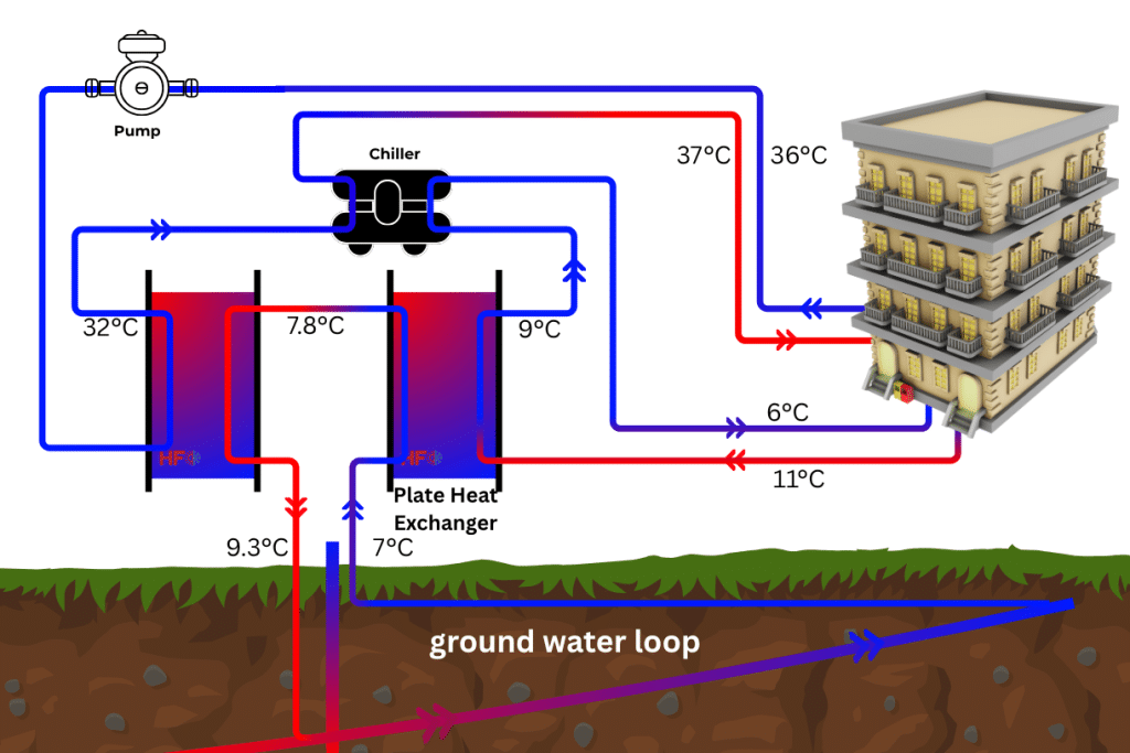
For projects involving heat exchangers, the PFD should clearly define inlet and outlet temperatures, flow rates, heat duty, fluids, and operating cases. This supports gasketed plate heat exchanger selection, shell and tube heat exchanger design, HTRI review, utility sizing, and technical procurement.
- Does the PFD match the latest heat and material balance?
- Are normal, minimum, maximum, start-up, shutdown, and upset cases defined?
- Are heat exchanger duties and pressure drop limits realistic?
- Are control loops shown logically before the P&ID is developed?
- Are utility users and utility loads clearly identified?
- Are recycle, bypass, relief, vent, and drain concepts understood?
What Mechanical and Static Equipment Teams Must Check
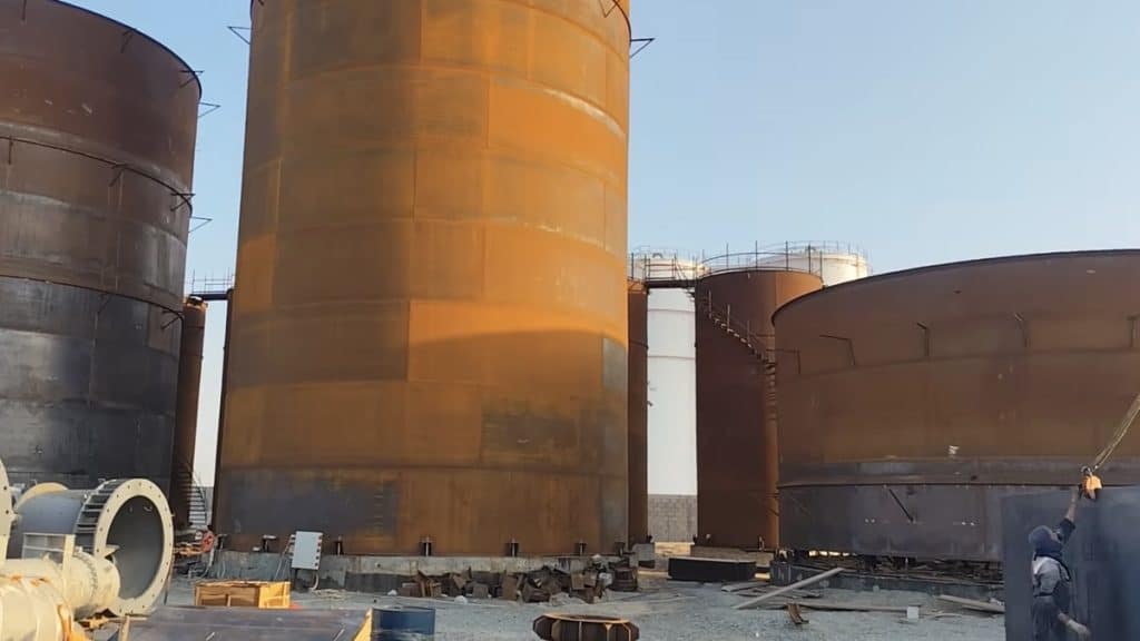
Mechanical engineers use PFDs and P&IDs to understand equipment service, nozzles, design conditions, material requirements, inspection needs, and operating constraints. A pressure vessel, storage tank, heat exchanger, separator, column, or skid package cannot be specified correctly if the P&ID is incomplete.
For static equipment, teams should check design pressure, design temperature, corrosion allowance, material class, insulation, nozzle schedule, relief connection, drains, vents, manways, inspection access, supports, and design code. Heating Formula provides ASME Section VIII pressure vessel design and static equipment engineering support for industrial projects.
- Are equipment design pressure and design temperature clearly defined?
- Are all nozzles shown and tagged correctly?
- Are drains, vents, manways, relief connections, and instrument connections shown?
- Does the P&ID match the equipment datasheet?
- Are materials compatible with process fluids and cleaning chemicals?
- Are API 650, API 620, ASME Section VIII, or other code requirements identified where relevant?
What Piping and Layout Teams Must Check
Piping engineers rely heavily on the P&ID. It defines line numbers, line classes, valves, equipment connections, drains, vents, bypasses, control valves, safety devices, and battery limits. Poor P&ID quality leads to poor piping layout, unclear line lists, missing valves, difficult maintenance access, and stress analysis problems.
For high-temperature systems, steam lines, pump suction lines, pressure vessels, heat exchangers, and modular skids, piping stress analysis may be required. Heating Formula supports piping design and stress analysis, including CAESAR II-based review where required by the project.
- Are line sizes, line numbers, and line classes consistent?
- Are isolation valves placed for operation and maintenance?
- Are drains and vents located correctly?
- Are bypasses justified and controlled?
- Are control valves and instruments accessible?
- Are thermal expansion, nozzle loads, support locations, and stress-sensitive lines considered?
What Procurement Engineers Must Check
Procurement engineers should not issue RFQs using incomplete or inconsistent PFDs and P&IDs. Vendors need clear datasheets, duty conditions, nozzle requirements, materials, inspection scope, controls, package limits, and document requirements. Otherwise, every supplier quotes different assumptions, and the technical bid evaluation becomes unreliable.
For example, a heat exchanger RFQ should not include only duty and flow rate. It should also define fluids, inlet and outlet temperatures, allowable pressure drop, design pressure, design temperature, materials, fouling allowance, cleaning requirements, nozzle sizes, connection standards, inspection requirements, and documentation. This is where technical procurement support and vendor document review become important.
- Are equipment datasheets aligned with the latest PFD and P&ID?
- Are vendor battery limits clearly marked?
- Are all required nozzles, instruments, valves, and package connections included?
- Are inspection and test requirements defined?
- Are vendor document submission requirements clear?
- Can different vendor offers be compared on the same technical basis?
Common Mistakes in PFD and P&ID Development
The most common mistake is treating the PFD and P&ID as drawings only, instead of using them as engineering control documents that connect process design, equipment selection, piping, controls, safety, procurement, and operation.
- Starting detailed engineering before the design basis is approved.
- Using old process simulation data while updating the drawing manually.
- Showing equipment on the PFD but missing its drain, vent, bypass, or isolation details on the P&ID.
- Not defining operating cases before heat exchanger or pump selection.
- Using inconsistent equipment tags between PFD, P&ID, equipment list, and datasheets.
- Leaving vendor package limits unclear.
- Ignoring maintenance access and isolation requirements.
- Not reviewing P&IDs with operations, maintenance, and safety teams before procurement.
Checklist: What to Confirm Before Engineering Starts
Before detailed engineering starts, industrial project teams should review the following checklist.
| Check Item | Why It Matters |
|---|---|
| Design basis approved | Prevents drawings from being built on assumptions |
| Heat and material balance complete | Controls equipment sizing and utility demand |
| PFD matches simulation | Prevents thermal duty, flow, and pressure errors |
| P&ID matches equipment datasheets | Prevents nozzle, valve, and instrument conflicts |
| Operating cases defined | Ensures equipment works under real plant conditions |
| Line list and equipment list consistent | Improves piping design, procurement, and document control |
| Control philosophy reviewed | Prevents missing loops, alarms, and operating logic |
| Relief, vent, and drain philosophy checked | Improves safety, commissioning, and maintenance |
| Vendor package limits defined | Reduces RFQ confusion and scope gaps |
| Operations and maintenance review completed | Improves accessibility, isolation, and long-term reliability |
Recommended Engineering Workflow
A reliable PFD and P&ID workflow reduces revisions and makes procurement more controlled. A practical sequence is:
- Start with the design basis: define process objective, fluids, operating cases, utilities, standards, assumptions, battery limits, and deliverables.
- Develop process simulation: use ASPEN HYSYS, ASPEN Plus, or equivalent methods where the process requires formal simulation.
- Prepare heat and material balance: define flow rates, temperatures, pressures, compositions, phases, and utility loads.
- Prepare the PFD: show main equipment, process streams, operating conditions, major controls, and utility connections.
- Develop the P&ID: add piping, valves, instruments, control loops, alarms, drains, vents, bypasses, safety devices, and package limits.
- Cross-check lists and datasheets: align equipment list, line list, instrument list, valve list, and equipment datasheets.
- Perform interdisciplinary review: involve process, mechanical, piping, instrument, electrical, safety, procurement, operations, and maintenance teams.
- Issue for RFQ or detailed design: release drawings only after revision control, comments, and project assumptions are clear.
- Review vendor documents: check vendor drawings and calculations against the latest PFD, P&ID, datasheet, and project specification.
How PFD and P&ID Affect Heat Exchanger Projects
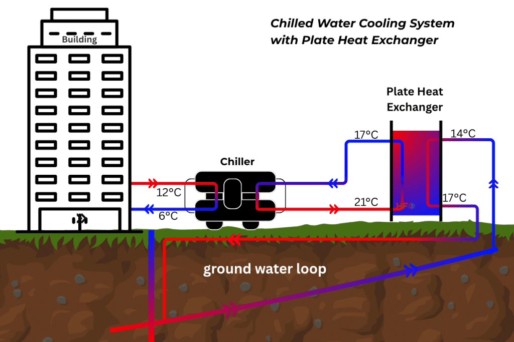
Heat exchanger projects are strongly affected by PFD and P&ID quality. The PFD defines duty, fluids, flow rates, temperatures, and utilities. The P&ID defines isolation valves, bypasses, control valves, drains, vents, instruments, safety devices, and maintenance arrangement.
For gasketed plate heat exchangers, the P&ID should show isolation, bypass, temperature indicators, pressure indicators, drains, vents, and cleaning connections where required. For shell and tube heat exchangers, the team should also consider bundle removal space, nozzle orientation, thermal expansion, relief case, and piping loads.
Heating Formula supports gasketed plate heat exchanger selection, shell and tube heat exchanger engineering, HTRI thermal design review, process simulation, and vendor document review for industrial heat exchanger projects.
How PFD and P&ID Support HAZOP and Safety Review
A HAZOP-ready P&ID should be complete enough to support systematic safety review. Missing instruments, unclear valve positions, incomplete relief paths, undefined bypasses, and unclear package limits can make safety review weak or delay the study.
For Oil & Gas and process plants, the P&ID should support review of overpressure, vacuum, reverse flow, blocked outlet, pump deadhead, thermal expansion, high temperature, low flow, contamination, instrument failure, utility failure, and maintenance isolation scenarios.
FAQ
What is the main difference between PFD and P&ID?
A PFD shows the main process flow, equipment, stream conditions, and heat and material balance. A P&ID shows detailed piping, valves, instruments, control loops, alarms, drains, vents, relief devices, and operating connections.
Which comes first, PFD or P&ID?
The PFD normally comes first because it defines the process route and main conditions. The P&ID is then developed from the approved PFD, design basis, equipment requirements, and control philosophy.
Can procurement start from a PFD only?
For early budget estimates, a PFD may be enough in some cases. For serious RFQ, technical bid evaluation, and purchase order preparation, equipment datasheets and developed P&IDs are usually required to avoid missing valves, instruments, nozzles, package limits, and inspection requirements.
Why are P&IDs important for heat exchanger selection?
P&IDs show how the heat exchanger will be connected, isolated, bypassed, drained, vented, controlled, and maintained. These details affect nozzle arrangement, pressure drop, operating flexibility, cleaning, safety, and procurement scope.
What makes a P&ID HAZOP-ready?
A HAZOP-ready P&ID should show equipment, line numbers, valve positions, instruments, control loops, alarms, relief devices, drains, vents, bypasses, package limits, and operating connections clearly enough for systematic safety review.
Who should review PFDs and P&IDs before engineering starts?
Process, mechanical, piping, instrumentation, electrical, safety, procurement, operations, and maintenance teams should review the drawings. This helps detect errors before they become procurement mistakes or site problems.
Can Heating Formula prepare PFDs and P&IDs?
Yes. Heating Formula supports industrial clients with PFD and smart P&ID engineering, process simulation, heat exchanger selection, static equipment design, piping design, procurement support, and vendor document review.
About Heating Formula
Heating Formula is an Istanbul-based engineering and industrial heat exchanger solutions provider serving Oil & Gas, HVAC, petrochemical, food & beverage, pharmaceutical, power generation, marine, mining, steel, ethanol, and paper mill applications.
The company supports clients with process design and engineering consultancy, heat exchanger engineering, process simulation, static equipment design, piping design, 3D modular skid design, procurement support, PFD and smart P&ID engineering, and OEM-compatible gasketed plate heat exchanger solutions.
Conclusion
A PFD explains the process. A P&ID explains how the process will be controlled, protected, isolated, operated, and maintained. Industrial project teams should confirm both before engineering, procurement, and construction move forward.
Before detailed engineering starts, check the design basis, heat and material balance, simulation data, equipment list, line list, instrument list, datasheets, control philosophy, safety requirements, package limits, and vendor interfaces. This prevents technical gaps from moving into procurement and site execution.
Heating Formula can support industrial projects with PFD and smart P&ID engineering, process simulation, heat exchanger selection, static equipment design, piping design and stress analysis, procurement engineering support, and vendor document review.
Further Reading
- OSHA Process Safety Management overview: https://www.osha.gov/process-safety-management
- HSE UK guidance on process safety leadership: https://www.hse.gov.uk/processsafety/
- ASME pressure vessel code information: https://www.asme.org/codes-standards
- API standards overview: https://www.api.org/products-and-services/standards