Plate Heat Exchangers for HVAC Chilled Water Systems
A plate heat exchanger in an HVAC chilled water system transfers cooling between two water circuits without mixing them. Engineers use it to separate chillers, cooling towers, district cooling networks, heat pumps, and building loops while keeping the required supply and return temperatures stable.
For many comfort cooling projects, the important question is not simply “what size heat exchanger do I need?” The real question is whether the selected plate heat exchanger can achieve the required temperature approach at the available flow rate and pressure drop.
Where the Plate Heat Exchanger Fits in an HVAC System
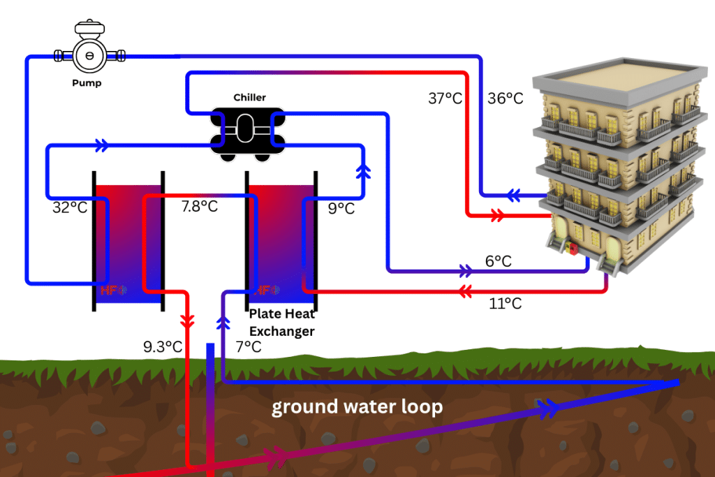
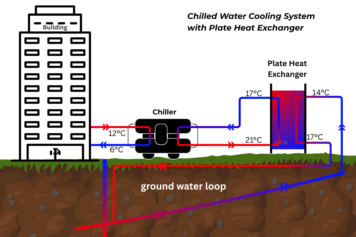
In a typical chilled water system, one side of the plate heat exchanger is connected to the cooling source and the other side is connected to the building circuit. The cooling source may be a chiller, cooling tower, dry cooler, district cooling network, seawater loop, geothermal loop, or mine water loop.
- Primary side: the cooling source or plant loop.
- Secondary side: the building chilled water loop feeding fan coils, AHUs, chilled beams, or process loads.
- Purpose: transfer cooling while isolating pressure, water quality, glycol content, and maintenance risk.
Why 6/13 C and 7/14 C Are Common HVAC Temperatures
Chilled water systems often use supply temperatures around 6-7 C and return temperatures around 12-14 C because this range gives a practical balance between cooling capacity, coil performance, humidity control, pipe size, and pump energy.
If water enters the building at 6 C and returns at 13 C, the water has gained 7 C from the building. For water, the quick flow estimate is:
Flow rate (m3/h) = Capacity (kW) / (1.163 x Delta T)For a 1500 kW chilled water duty with a 7 C temperature rise:
Flow rate = 1500 / (1.163 x 7)
Flow rate = 184 m3/h approximately
This is why temperature difference matters. A smaller Delta T needs more water flow. A larger Delta T allows lower flow, but the terminal units and control strategy must support it.
The Most Important HVAC Sizing Check: Approach Temperature
Approach temperature is the closest temperature difference between the hot and cold streams. In HVAC plate heat exchanger selection, a tight approach means the heat exchanger needs more effective heat transfer area.
| Duty Example | End 1 Difference | End 2 Difference | Difficulty |
|---|---|---|---|
| 14 C to 7 C / 6 C to 13 C | 14 – 13 = 1 C | 7 – 6 = 1 C | Very tight |
| 14 C to 7 C / 5 C to 13 C | 14 – 13 = 1 C | 7 – 5 = 2 C | Easier |
| 14 C to 8 C / 6 C to 12 C | 14 – 12 = 2 C | 8 – 6 = 2 C | Moderate |
A 1 C approach is possible, but it is demanding. It usually requires more plates, more area, clean water, realistic fouling factors, and careful pressure drop control. If a datasheet claims a tight approach with surprisingly few plates, engineers should check the original software output and not only the manually prepared offer sheet.
When HVAC Engineers Use Plate Heat Exchangers
- Chiller isolation: separates the chiller evaporator from a large building loop.
- District cooling connection: transfers cooling from the utility network to the building without mixing water.
- Free cooling: uses outdoor air, cooling tower water, seawater, or groundwater when available temperatures are low enough.
- Heat pump systems: connects condenser or evaporator loops to a building circuit.
- Retrofits: protects new equipment from old building pipework and poor water quality.
Data Required Before Selecting an HVAC Plate Heat Exchanger
A reliable selection starts with complete duty data. Missing one item can change the number of plates, connection size, pressure drop, and final price.
- Cooling capacity in kW.
- Inlet and outlet temperatures on both sides.
- Fluid type, including glycol percentage if used.
- Maximum allowable pressure drop on each side.
- Design pressure and design temperature.
- Fouling factor or water quality expectation.
- Material requirements for plates, gaskets, and connections.
- Installation limits such as frame length, connection orientation, and service space.
Quick Engineering Checks Before Approving the Datasheet
Before approving an HVAC plate heat exchanger datasheet, engineers should perform three quick checks: heat balance, approach temperature, and pressure drop. These checks catch many undersized or incorrectly edited selections.
- Heat balance: both sides should match the stated kW within an acceptable tolerance.
- Flow rate: for water, use kW / (1.163 x Delta T) as a quick check.
- Approach: confirm the closest temperature difference used in the software matches the client duty.
- Pressure drop: confirm the selected unit does not exceed pump limits.
- Plate count and area: compare with similar projects or a second supplier if the duty is tight.
For early-stage sizing, use the Heating Formula heat exchanger calculator. For project selection, ask for a complete manufacturer datasheet and verify it against the method in the plate heat exchanger sizing guide.
Best Applications for HVAC Plate Heat Exchangers
| Application | Why PHE Works Well | Key Selection Risk |
|---|---|---|
| Commercial chilled water | Compact size and close approach | Low approach requires enough plates |
| District cooling | Hydraulic separation from utility network | Pressure rating and metering accuracy |
| Free cooling | Uses low-temperature ambient or water source | Seasonal temperature variation |
| Heat pump evaporator loop | Protects heat pump from source-water quality | Glycol and fouling assumptions |
| Retrofit plant rooms | Small footprint compared with shell and tube | Access for maintenance and gasket replacement |
FAQ
Can a plate heat exchanger achieve a 1 C approach in HVAC?
Yes, a plate heat exchanger can achieve a 1 C approach in some HVAC duties, but the selection must use enough heat transfer area and realistic fouling assumptions. A 1 C approach is tight, so small changes in temperature, flow, or fouling can reduce performance.
Is a plate heat exchanger better than a shell and tube exchanger for chilled water?
For clean water HVAC duties, a gasketed plate heat exchanger is often more compact and can achieve closer approach temperatures than a shell and tube exchanger. Shell and tube designs may be preferred for very dirty fluids, very high pressures, or specific mechanical design requirements.
What causes poor chilled water heat exchanger performance?
Poor performance is usually caused by undersizing, fouling, trapped air, incorrect flow rate, reversed connections, wrong glycol assumptions, or a datasheet based on different temperatures than the real project duty.