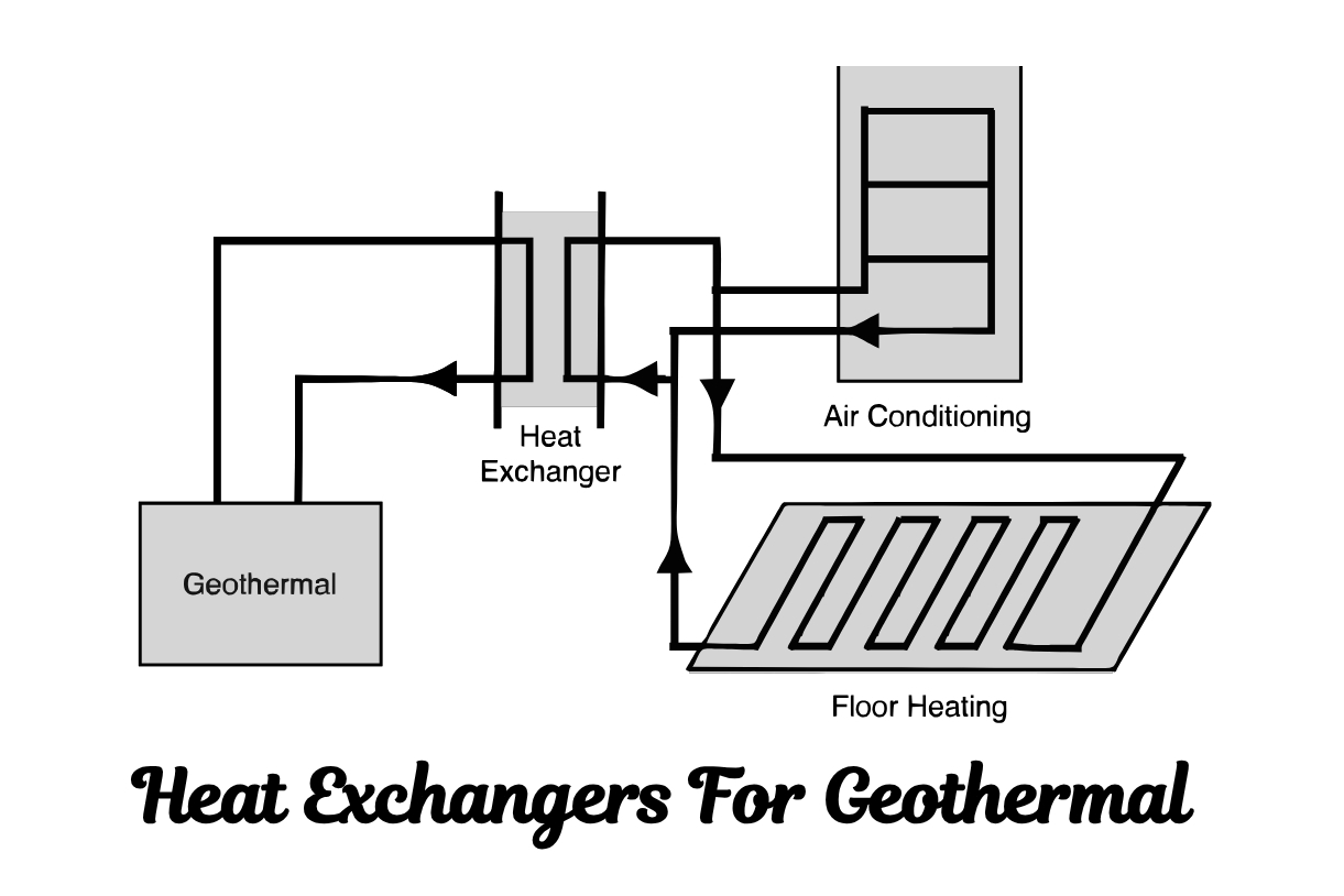
Why Does Correct PHE Sizing Matter More Than You Think?
Sizing a plate heat exchanger isn’t just about picking a model from a catalog; it’s a foundational engineering task with long-term consequences. The right size ensures your system operates at peak efficiency, while a mismatch can trigger a cascade of operational and financial problems.
Critical Impact: Improper sizing can reduce system efficiency by 15-30% and increase operational costs significantly. Both undersizing and oversizing create serious performance issues that compound over time.
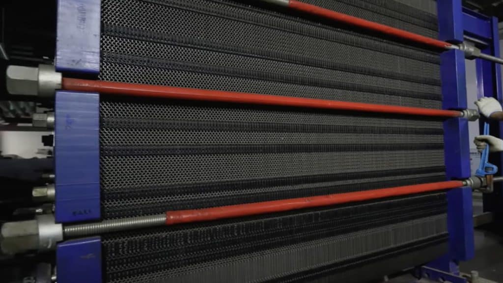
What Are the Consequences of Improper Sizing?
| Issue | Undersized PHE | Oversized PHE |
|---|---|---|
| Thermal Performance | ✗ Fails to meet required heat transfer | ✗ Poor thermal control |
| Flow Characteristics | Excessive pressure drop | Too low velocity → increased fouling |
| Process Impact | Bottleneck → reduced production | Inefficient energy usage |
| Capital Cost | Lower initial cost | Higher unnecessary expense |
| Operating Cost | High energy to compensate | Frequent cleaning required |
| Maintenance | Component stress & wear | Accelerated fouling |
What Are the Rewards of Right-Sizing?
- Optimal Performance: A correctly sized PHE integrates seamlessly into your system, delivering the exact thermal performance required.
- Reduced Footprint: PHEs are known for being compact, and right-sizing ensures you’re not wasting valuable plant floor space.
- Energy and Cost Savings: Optimized plate geometry and surface area lead to highly efficient heat transfer, which directly translates to lower energy bills.
- Longer Maintenance Intervals: When a PHE operates within its designed parameters, issues like fouling and wear on components like gaskets are minimized, extending the time between services.
What Are the Fundamental Calculations for Sizing a PHE?
At its core, sizing a plate heat exchanger revolves around a fundamental heat transfer equation. This formula connects the key variables that dictate the exchanger’s performance.
Q = U × A × ΔTLMTD
Let’s break down what each of these components means for your project:
Key Variables Explained:
- Q (Heat Duty): Total amount of heat (in kW or BTU/hr) that needs to be transferred between the two fluids. This is the first thing you need to define, based on your process requirements, flow rates, and the desired temperature change.
- U (Overall Heat Transfer Coefficient): Measure of the heat exchanger’s overall efficiency (in W/m²K). It’s influenced by the thermal conductivity of the plate material, the properties of the fluids, the turbulence created by the plate pattern, and any resistance from fouling. A higher U-value means a more efficient exchanger.
- A (Heat Transfer Area): Total surface area (in m²) of the plates across which heat will be exchanged. In the sizing process, this is often the variable you are solving for to determine how many plates are needed.
- ΔTLMTD (Log Mean Temperature Difference): The temperature difference between the hot and cold fluids changes as the fluids move through the exchanger. The LMTD provides a more accurate average temperature difference, or “driving force,” for the heat transfer. A counter-current flow arrangement typically yields the highest LMTD and is, therefore, the most efficient configuration.
Once you have these values, you can rearrange the formula to solve for the required area:
A = Q / (U × ΔTLMTD)
For a quick and reliable starting point in your calculations, we recommend using our online Heat Exchanger Calculator. This tool can help you get preliminary estimates and understand the relationships between these key variables.
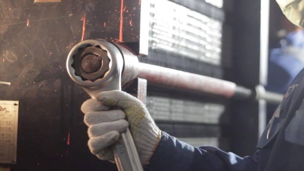
How Do Plate Design and Material Impact Performance?
Beyond the numbers, the physical characteristics of the plates themselves are a major factor in performance.
What Plate Patterns Are Available and How Do They Affect Performance?
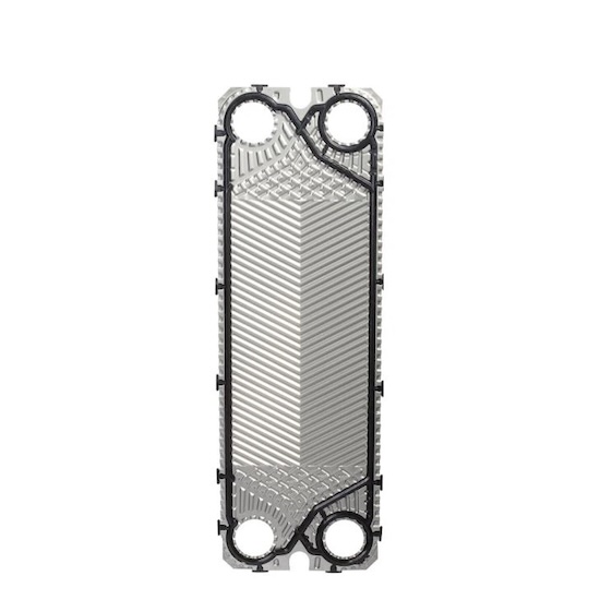
The corrugated patterns on heat exchanger plates, such as the common herringbone pattern, are not just for structural integrity; they are engineered to create turbulence. This turbulence disrupts the “boundary layer” of the fluid against the plate surface, dramatically increasing the heat transfer coefficient (U-value).
| Pattern Type | Chevron Angle | Turbulence Level | Heat Transfer Efficiency | Pressure Drop | Best Applications |
|---|---|---|---|---|---|
| Acute-angle (High-Theta) | 60° – 70° | ✓ Very High | ✓ Excellent | High | Clean fluids, high performance requirements |
| Medium-angle | 45° – 60° | Moderate | ✓ Good | Medium | General purpose, balanced design |
| Obtuse-angle (Low-Theta) | 20° – 45° | Lower | Moderate | ✓ Low | Viscous fluids, strict pressure limits |
| Mixed Arrangements | Variable | Customized | ✓ Optimized | Balanced | Complex applications, optimal performance |
Design Consideration: Manufacturers are constantly innovating with advanced patterns like the Sondex “Fishbone” or Alfa Laval “CurveFlow” to further enhance distribution and efficiency. When selecting a plate pattern, always balance heat transfer requirements with allowable pressure drop.
Which Plate Material Should You Choose for Your Application?
Choosing the right material is essential for longevity and reliability, especially when dealing with corrosive fluids or high temperatures.
| Material | Temperature Range | Corrosion Resistance | Cost | Typical Applications | Chloride Resistance |
|---|---|---|---|---|---|
| 304 Stainless Steel | -20°C to 150°C | Good | ✓ Low | General HVAC, low-chloride water | Limited (< 200 ppm) |
| 316 Stainless Steel | -20°C to 200°C | ✓ Very Good | Moderate | Food & beverage, HVAC, general industrial | Good (< 1000 ppm) |
| Titanium | -200°C to 300°C | ✓ Excellent | High | Seawater, brine, high-chloride fluids | ✓ Excellent (unlimited) |
| C-276 Hastelloy | -50°C to 400°C | ✓ Superior | Very High | Strong acids, chemical processing | ✓ Excellent |
| 254 SMO | -20°C to 300°C | ✓ Superior | Very High | Aggressive chemicals, oil & gas | ✓ Excellent |
Heating Formula Advantage: We supply a full range of plates and gaskets in all these materials, ensuring you can find the perfect match for your application. Our GPHE Spare Parts are fully compatible with major OEM brands like Alfa Laval, Sondex, APV SPX, Funke, Schmidt, Vicarb, Gea, and Tranter, offering a high-quality, cost-effective solution.
How Do You Balance High Performance with Low Pressure Drop?
One of the most critical trade-offs in PHE sizing is balancing heat transfer efficiency with pressure drop. The very features that enhance heat transfer—namely, turbulent flow—also increase the resistance the fluid encounters, leading to a drop in pressure from the inlet to the outlet.
An excessive pressure drop is undesirable because it requires more pumping power, which directly translates to higher energy consumption and operational costs. The goal is to design a PHE that creates enough turbulence for efficient heat transfer while keeping the pressure drop within the limits your system can handle. This “sweet spot” ensures optimal performance without overburdening your pumps.
Engineering Rule of Thumb: Port pressure drop should not exceed 33% of total system pressure drop. Exceeding this can lead to flow maldistribution and reduced efficiency. For more details, see our comprehensive guide on port pressure drop optimization.
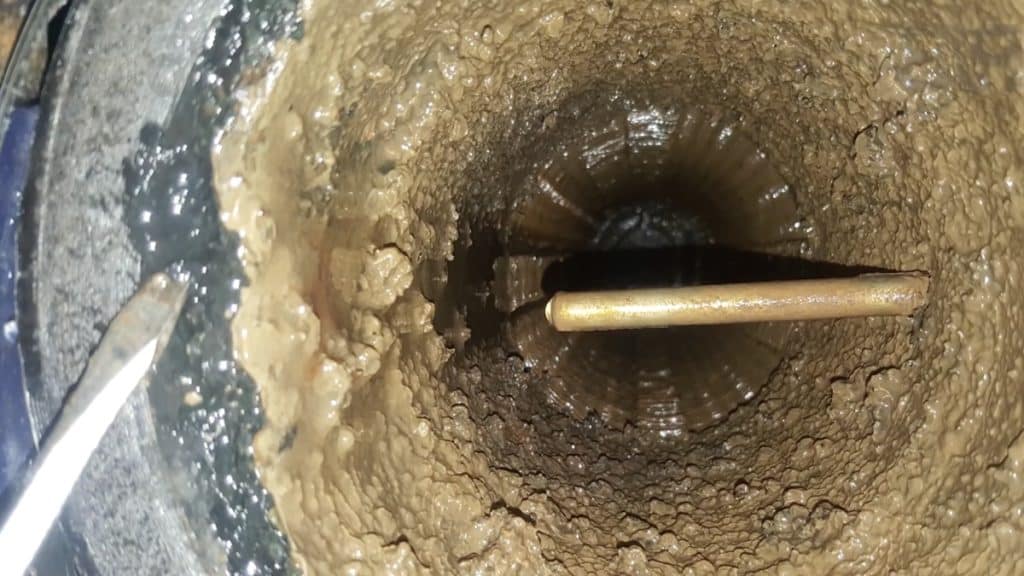
What Role Does Fouling Play in Sizing?
Fouling is the gradual accumulation of unwanted deposits—such as mineral scale, sediment, or biological matter—on the heat transfer surfaces. This is a critical consideration in nearly every industry, from scaling in power plant cooling systems to product buildup in food processing.
Fouling acts as an insulating layer, which reduces the overall heat transfer coefficient (U) and degrades the exchanger’s performance over time. To account for this, engineers include a fouling factor in the sizing calculation. This factor adds a margin of safety by requiring a larger heat transfer area (more plates) than would be needed for perfectly clean conditions.
| Fluid Type | Typical Fouling Factor (m²K/W) | Fouling Tendency | Recommended Cleaning Frequency |
|---|---|---|---|
| Distilled Water | 0.00009 | ✓ Very Low | Annual |
| Treated Boiler Feedwater | 0.00018 | Low | 6-12 months |
| Cooling Tower Water | 0.00044 | Moderate | 3-6 months |
| City Water (Hard) | 0.00053 | Moderate-High | 3-6 months |
| Seawater | 0.00088 | High | 2-4 months |
| Process Fluids (Food) | 0.00018 – 0.00053 | Variable | Weekly – Monthly |
Self-Cleaning Effect: Modern plate designs with high turbulence can help minimize fouling by creating a “self-cleaning” effect, where the fluid’s shear stress helps to scrub deposits off the surface. This is particularly effective with high-theta chevron patterns in applications with moderate fouling tendencies.
Your Partner in Thermal Solutions
Sizing a plate heat exchanger is a detailed process where every variable matters. Getting it right from the start saves time, money, and future headaches.
At Heating Formula, we are more than just a manufacturer; we are your partner in thermal engineering. As a leading heat exchanger specialist in Turkey, we supply high-quality Gasketed Plate Heat Exchangers, Shell & Tube exchangers, and a comprehensive inventory of compatible spare parts to industries worldwide. Our product range includes plates made from 316/304 Stainless Steel, Titanium, C-276 Hastelloy, and 254 SMO, along with durable gaskets in EPDM, NBR, and Viton.
Whether you are designing a new system or looking to optimize an existing one, our experts are here to help. Explore our GPHE Selection page for more information or contact us today for a consultation tailored to your unique needs.
Frequently Asked Questions (FAQ)
1-What happens if a plate heat exchanger is oversized?
An oversized PHE can lead to excessively low fluid velocity, which reduces turbulence and can significantly increase the rate of fouling. It also represents a higher-than-necessary capital cost and can make process control more difficult.
2-What are the signs that my PHE is undersized?
An undersized heat exchanger will consistently fail to achieve the desired outlet temperatures for the hot and cold fluids. This creates a process bottleneck, forcing you to reduce production rates or accept lower-quality output.
3-How do I know when my PHE needs cleaning?
The most common indicators are a gradual decrease in thermal performance (e.g., outlet temperatures are no longer meeting targets) and a steady increase in the pressure drop across the unit. Regular monitoring of these parameters is key.
4-What is the typical lifespan of a plate heat exchanger gasket?
Gasket lifespan varies widely depending on the operating temperature, the chemical compatibility of the fluid, and the gasket material (e.g., EPDM, NBR, Viton). Under mild conditions, gaskets can last for many years, but in high-temperature or aggressive chemical applications, their lifespan could be as short as one year. It’s crucial to select the right material, which you can find in our GPHE Spare Parts catalog.
5-How do I choose between titanium and stainless steel plates?
Titanium plates are the standard for applications involving high-chloride fluids like seawater, brine, or chlorinated water, due to their superior corrosion resistance. For most other duties in industries like HVAC, food processing, and general manufacturing, stainless steel (typically 316 grade) offers an excellent balance of performance and cost-effectiveness.
Sources
- Webb, R. L., & Eckert, E. R. G. (1972). Application of rough surfaces to heat exchanger design. International Journal of Heat and Mass Transfer, 15(8), 1647-1658.
- Kaur, I., & Singh, P. (2021). State-of-the-art in heat exchanger additive manufacturing. International Journal of Heat and Mass Transfer, 178, 121600.
- Hisaka Works, Ltd. (2022). Plate Heat Exchanger Maintenance Manual.
- Sondex A/S (Danfoss). (2019). Gasketed Plate Heat Exchangers (DN 150 / 6″) Data Sheet.
- Tranter, Inc. (2023). A Project Engineer’s guide to properly sizing a plate heat exchanger.
For additional technical information on heat exchanger sizing and selection, visit the Plate Heat Exchanger Wikipedia page.