AutoCAD Plant 3D: Intelligent Piping Layout, Routing & Isometrics
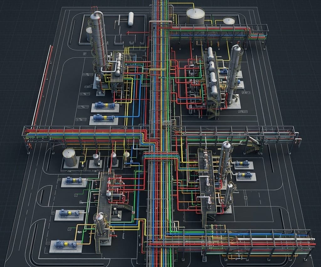
Designing the physical routing of thousands of meters of interconnected industrial piping is one of the most spatially complex tasks in plant engineering. AutoCAD Plant 3D is the specialized intelligent CAD environment our team uses to accomplish this with precision — producing clash-free 3D piping layouts that automatically generate accurate isometric drawings and material take-offs. It is the essential piping design companion within our engineering design and consultancy workflow, working directly alongside our piping design and stress analysis services.
What is AutoCAD Plant 3D?
AutoCAD Plant 3D (developed by Autodesk) is a specialized plant design software built on the AutoCAD platform, specifically engineered for industrial piping layout, equipment placement, and structural steel modeling. Unlike generic AutoCAD, every pipe, fitting, and valve in Plant 3D is an intelligent data-rich object that knows its specification, size, material, and connectivity — enabling automatic generation of isometrics, material take-offs, and P&ID connectivity verification.
Where SolidWorks excels at the detailed mechanical design of individual equipment items, AutoCAD Plant 3D excels at routing the fluid transfer network between them — handling hundreds of pipe lines across an entire facility in a single coordinated 3D model that all engineering disciplines can access simultaneously.
Core Capabilities in Our Piping Engineering Work
We use AutoCAD Plant 3D across the full piping engineering scope of major industrial projects, from initial plot plan development through to final fabrication isometrics.
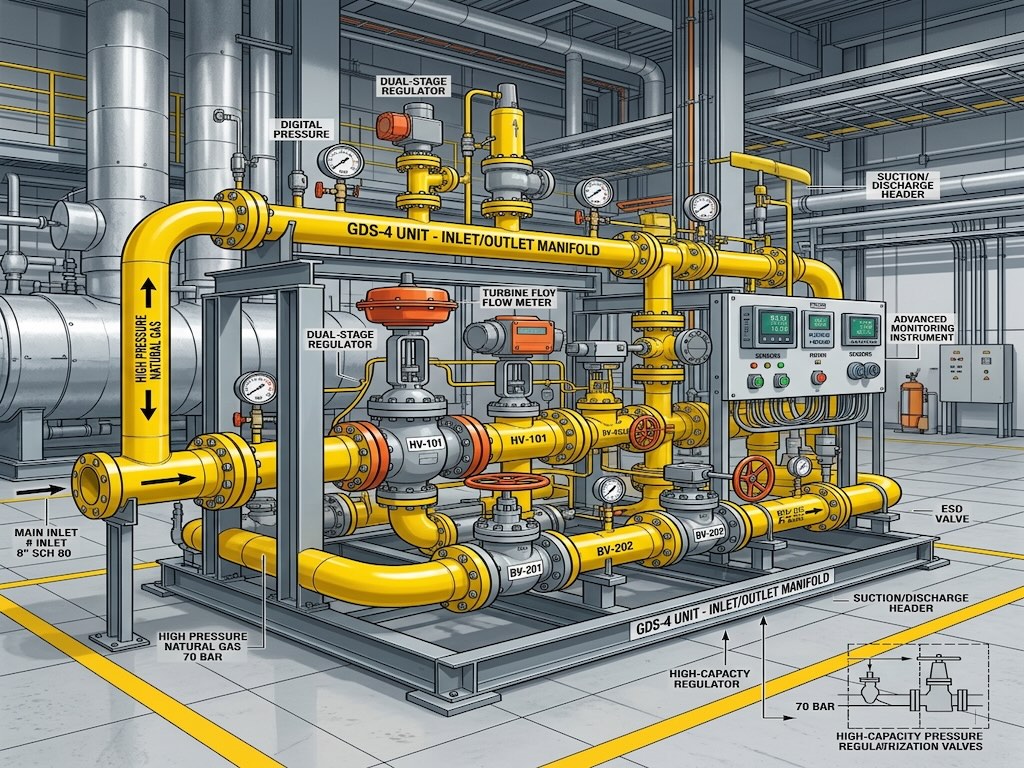
- 3D Piping Layout & Routing: Placing all pipe lines on their correct pipe specification, routing them through the facility with correct slope, clearances, and maintenance access.
- Equipment & Nozzle Placement: Positioning vessels, heat exchangers, pumps, and compressors exactly as defined in the equipment layout drawings, with nozzle orientations matched to the P&ID documentation.
- Clash Detection: Running automated interference checks to find and resolve all spatial conflicts between pipes, equipment, structural steel, and cable trays before fabrication.
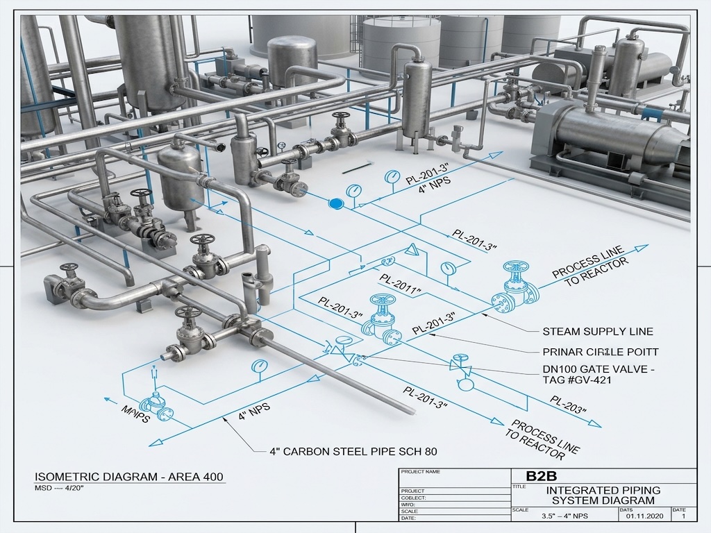
- Automatic Isometric Generation: Extracting dimensioned pipe isometric drawings directly from the 3D model with automatic bill of materials — eliminating manual drafting errors.
- Material Take-Off (MTO) Reports: Generating precise, specification-compliant material lists for procurement, directly from the intelligent pipe objects in the model.
AutoCAD Plant 3D vs. Manual 2D Piping Design
| Design Task | Manual 2D CAD Drafting | AutoCAD Plant 3D |
|---|---|---|
| Clash Detection | Manual visual checking — high miss rate | Automated 3D interference reporting — zero missed clashes |
| Isometric Generation | Manually drafted — slow, error-prone | Auto-extracted from 3D model — instant, accurate |
| Material Take-Off | Manual counting from drawings — unreliable | Auto-generated from intelligent pipe objects — 100% accurate |
| Design Revisions | Re-drafting every affected view manually | Parametric update — change once, all views update |
| Stress Analysis Handoff | Manual coordinate extraction for CAESAR II | Direct neutral file export to CAESAR II |
Engineering Tip: Always model pipe support locations in AutoCAD Plant 3D before sending the stress analysis to CAESAR II. The support positions and types defined in the 3D model must exactly match what is entered into CAESAR II — any discrepancy creates a stress model that does not represent the real facility.
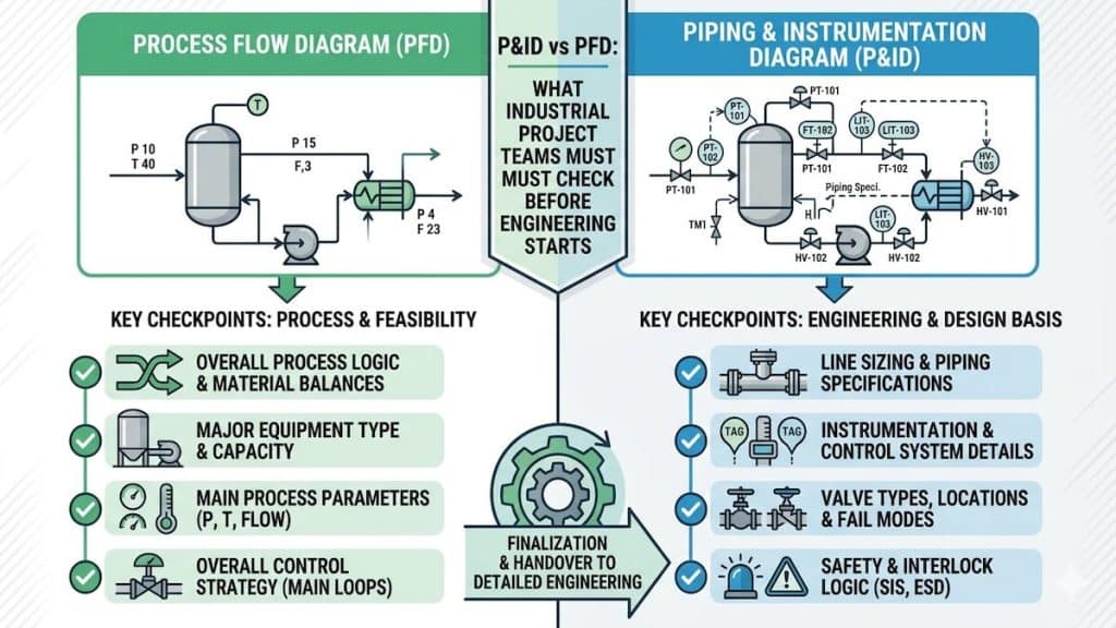
From P&ID to Fabrication: The AutoCAD Plant 3D Workflow
AutoCAD Plant 3D sits at the center of the engineering-to-fabrication pipeline, receiving data upstream from the P&ID development phase and delivering model outputs downstream to stress analysis and fabrication.
- P&ID import and line list creation — every pipe line tag from the P&ID is registered in the Plant 3D project database with its assigned pipe specification.
- Equipment models placed — vessel, pump, and heat exchanger 3D models positioned on the plot plan at their design coordinates.
- Pipe routing performed — engineers route each line through the facility, selecting fittings, valves, and supports from the spec-driven component library.
- Clash detection run — interference report generated and all detected clashes resolved with routing adjustments.
- Stress-critical lines exported to CAESAR II — high-temperature and high-pressure lines exported for formal flexibility and stress analysis.
- Isometrics and MTO issued for fabrication — complete fabrication package extracted directly from the model and submitted to the pipe fabrication shop.
Frequently Asked Questions
What is the difference between AutoCAD and AutoCAD Plant 3D?
Standard AutoCAD is a general-purpose 2D and 3D drafting tool. AutoCAD Plant 3D is an industry-specific extension containing a full spec-driven pipe component library, P&ID integration, automatic isometric extraction, and clash detection — capabilities that general AutoCAD does not have.
What is a pipe isometric drawing?
A pipe isometric drawing is a 3D schematic representation of a single pipe line showing its routing, all fittings, valves, dimensions, weld numbers, and support locations. It is the primary fabrication document issued to a pipe fabrication shop and is automatically extracted from the AutoCAD Plant 3D model.
Can AutoCAD Plant 3D export to CAESAR II?
Yes. AutoCAD Plant 3D can export pipe geometry in neutral file formats (PCF — Piping Component File) that are directly importable into CAESAR II, enabling the stress analyst to build a validated model without re-entering all pipe coordinates and fittings manually.
What is a pipe specification in Plant 3D?
A pipe specification (pipe spec) is a controlled document that defines exactly which pipes, fittings, valves, and gaskets are permitted for a given service (based on temperature, pressure, and fluid). In AutoCAD Plant 3D, the spec is embedded in the software so engineers can only select components that are explicitly approved for each pipe line.
Clash-Free Piping Design Ready for Fabrication
A piping layout that clashes in the field costs exponentially more to fix than one resolved in AutoCAD Plant 3D. Our team delivers complete, clash-free 3D piping models with full isometric and material take-off packages — ready for immediate fabrication. Explore our complete piping design and analysis engineering services to see how AutoCAD Plant 3D fits into our end-to-end project delivery.