SolidWorks in Industrial Engineering: 3D Modeling & Equipment Design
In industrial engineering, the distance between a calculation and a physical fabricated asset is bridged by precision 3D modeling. SolidWorks is the parametric CAD environment our engineers use to translate verified mechanical calculations into exact, manufacturable geometry. From individual pressure vessel nozzle details to complete modular skid packages, SolidWorks is embedded throughout our engineering design and consultancy workflow as the primary 3D mechanical modeling platform.
What is SolidWorks Used for in Industrial Engineering?
SolidWorks (developed by Dassault Systèmes) is a parametric 3D CAD software platform widely used in mechanical and industrial engineering for the precise modeling of equipment, structures, and assemblies. In the process industry, it produces the General Arrangement (GA) drawings, fabrication details, and 3D assembly models that manufacturers need to build physical equipment exactly as designed.
Unlike 2D drafting tools, SolidWorks creates intelligent parametric models where changing one dimension automatically updates the entire assembly — eliminating the human error that plagues manual drawing revisions. This makes it the ideal companion to our static equipment design calculations performed in PV Elite, translating code-compliant wall thicknesses and nozzle dimensions into fully manufacturable 3D geometry.
How We Use SolidWorks Across Engineering Disciplines
SolidWorks is not a one-task tool in our workflow — it touches multiple engineering disciplines across a project lifecycle.
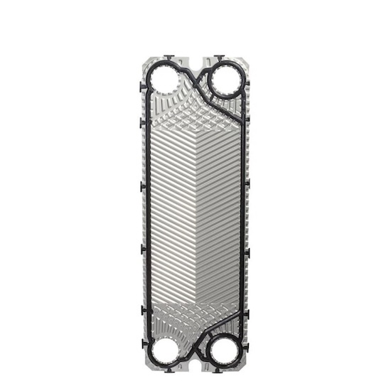
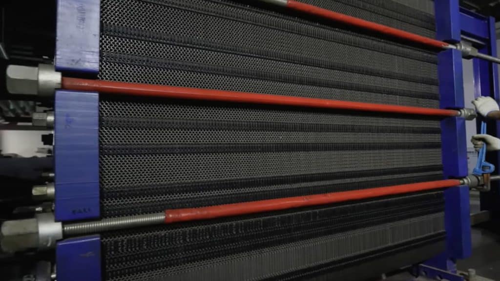
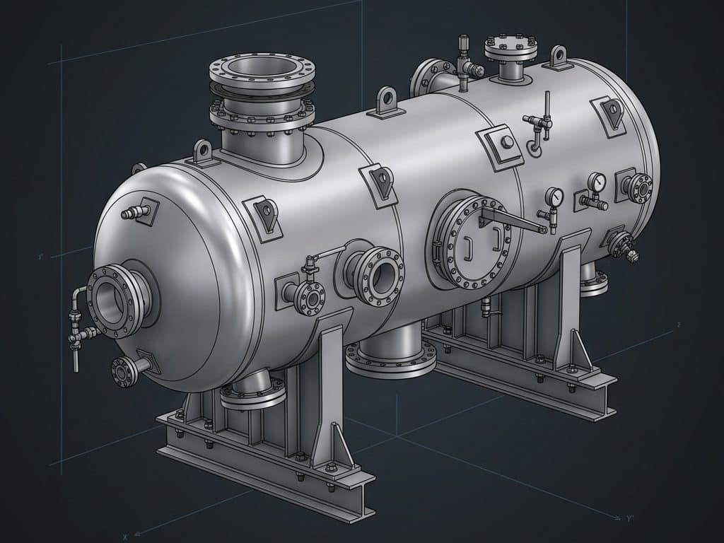
- Pressure Vessel 3D Modeling: Creating fully dimensioned 3D models of shell & tube heat exchangers, separators, and reactors with precise nozzle orientations ready for fabrication review.
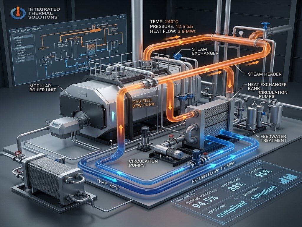
- Modular Skid Assemblies: Engineering complete structural steel frames, equipment layouts, and piping in a single 3D environment for our 3D modular skid design engagements.
- Structural Support Design: Modeling saddles, legs, skirts, and lifting lugs with geometry that directly feeds structural load calculations.
- GA & Fabrication Drawings: Auto-generating 2D drawing packages (front view, top view, section cuts, nozzle schedule) directly from the 3D model — eliminating transcription errors.
- Vendor Drawing Verification: Importing manufacturer-supplied 3D models to verify dimensional accuracy before approving them in our technical procurement review.
SolidWorks vs. AutoCAD: Key Differences for Industrial Projects
| Feature | SolidWorks | AutoCAD Plant 3D |
|---|---|---|
| Primary Use | Mechanical equipment & structural modeling | Plant piping layout & routing |
| Model Type | Parametric solid modeling | Intelligent pipe and equipment placing |
| Best For | Individual equipment detail design (vessels, skids) | Full plant piping network design and isometrics |
| Drawing Output | GA drawings, fabrication details, BOMs | Piping isometrics, plant layout, material take-offs |
| Clash Detection | Within equipment assemblies and skids | Full plant-level piping clash detection |
Engineering Tip: For complex modular skid projects, we use SolidWorks and AutoCAD Plant 3D together — SolidWorks builds the precise equipment models, and AutoCAD Plant 3D integrates them into the full piping network with accurate clash detection across the entire skid envelope.
From PV Elite Calculations to SolidWorks Model: The Workflow
Our static equipment engineering workflow uses a strict handoff process between calculation software and 3D modeling:
- PV Elite finalizes mechanical design — shell thickness, head type, nozzle dimensions, and support geometry confirmed per ASME code.
- SolidWorks model initiated — all calculated dimensions entered as parametric dimensions in the vessel model.
- Nozzle orientations set — exact azimuth and elevation angles positioned to match the piping design connection points.
- Support structure modeled — saddles, legs, or skirt designed in SolidWorks and cross-referenced against the foundation layout.
- GA drawings extracted — full 2D drawing package generated from the 3D model with section views, weld details, and nozzle schedule.
- Model issued for fabrication review — 3D file and 2D drawings submitted to the fabricator for shop review and clash checking against plant model.
Frequently Asked Questions
Is SolidWorks used in oil and gas engineering?
Yes. SolidWorks is widely used in oil and gas for the detailed 3D design of pressure vessels, heat exchangers, modular process skids, pipe supports, and structural equipment. It is particularly valued for producing high-quality fabrication drawing packages for custom-engineered equipment.
What is a General Arrangement (GA) drawing?
A General Arrangement (GA) drawing is a master engineering document showing the overall dimensions, nozzle positions, support locations, and key details of a piece of equipment. It is the primary document issued to fabricators and is always generated from a verified 3D model in SolidWorks to ensure dimensional accuracy.
What is parametric modeling in SolidWorks?
Parametric modeling means that every dimension in a SolidWorks model is driven by a value that can be changed — and when one dimension changes, all dependent geometry automatically updates. This ensures that a design revision never creates inconsistencies between different drawing views or components in an assembly.
Can SolidWorks detect clashes in a skid assembly?
Yes. SolidWorks includes an Interference Detection tool that automatically identifies any spatial overlaps between components in an assembly — catching physical conflicts between pipes, structural members, and equipment before they reach the fabrication shop.
Precision 3D Modeling for Reliable Fabrication
Every millimeter matters when a pressure vessel is being fabricated. Our SolidWorks models give fabricators unambiguous, fully dimensioned geometry with zero room for interpretation errors. Paired with our rigorous static equipment mechanical calculations and our complete modular skid design services, we ensure what is built is exactly what was designed.