Understanding Diagram Piping for Complex Industrial Facilities
The physical arteries of any industrial plant—from petrochemical refineries to pharmaceutical manufacturing—are defined by accurate diagram piping. Translating a conceptual process flow into a safe, constructible piping network requires a meticulous transition from 2D schematics to fully analyzed 3D layouts. A flawless diagram piping strategy prevents costly rework, ensures hydraulic efficiency, and maintains compliance with strict international codes like ASME B31.3.
What is Diagram Piping?
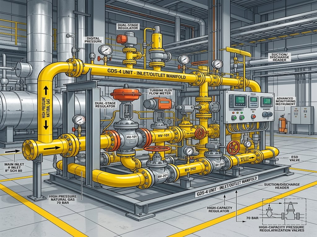
Diagram piping refers to the creation and interpretation of schematic drawings—specifically Piping and Instrumentation Diagrams (P&IDs) and Piping Isometrics—that dictate how fluids and gases move through a facility. It details exactly where pipes connect, the necessary valves and fittings, and provides the fundamental data required for rigorous piping stress analysis and physical construction.
The Evolution of a Piping Diagram
Piping does not go directly from a process engineer’s mind to a welder’s torch. The development of diagram piping follows a structured engineering workflow:
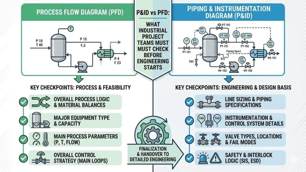
- Process Flow Diagram (PFD): Establishes the basic heat and mass balance. It shows only the major equipment and main process lines.
- Piping and Instrumentation Diagram (P&ID): Adds massive detail, including all pipe sizes, insulation classes, block valves, control loops, and drains. See our PFD/P&ID engineering services.
- 3D Piping Layout: A mechanical designer routes the physical pipes in a 3D CAD environment (like PDMS or SmartPlant 3D) based exactly on the P&ID.
- Piping Stress Analysis: Engineers use software like CAESAR II to ensure the 3D routed pipes will not fail due to thermal expansion or weight. Discover more about piping design analysis.
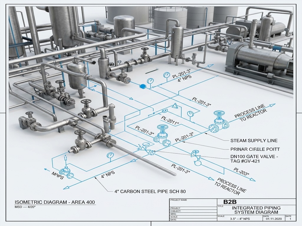
- Isometric Drawings (Isos): The final output given to the fabrication shop. Isometrics are non-scale, 3D representations of a single pipe spool, detailing every weld, cut length, and fitting required for assembly.
P&ID vs. Isometric Diagram Piping
A common hurdle for junior engineers is understanding the distinct difference between a P&ID and a Piping Isometric drawing. Both are critical forms of diagram piping, but they serve completely different purposes.
| Feature | P&ID (Piping & Instrumentation Diagram) | Piping Isometric (Iso) |
|---|---|---|
| Purpose | Logical process control and system architecture. | Physical fabrication and construction assembly. |
| Perspective | Flat, 2D logical schematic (no scale or direction). | 3D wireframe drawn on a 30-degree isometric grid. |
| Details Shown | Process logic, instrumentation loops, safety valves. | Exact pipe lengths, weld locations, and Bill of Materials. |
| Primary User | Process Engineers and Control Systems Engineers. | Pipefitters, Welders, and Construction Managers. |
Frequently Asked Questions
Why is isometric diagram piping not drawn to scale?
Isometrics are drawn out of scale to ensure all components are clearly visible. A massive 100-meter straight pipe run and a tiny cluster of complex valves must both fit on the same sheet of paper, so dimensions are written numerically rather than drawn proportionally.
What is a Piping Class?
A piping class (or pipe spec) is a standardized document that dictates exactly what materials must be used for a specific fluid service. It defines the allowed pipe material, wall thickness, flange ratings, and gasket types based on pressure and temperature.
How does thermal expansion affect diagram piping?
Hot fluids cause steel pipes to expand significantly in length. If the piping layout does not include expansion loops or specialized supports to absorb this movement, the expanding pipe can crush equipment nozzles or tear itself off the rack.
What is a Bill of Materials (BOM) on a piping diagram?
The BOM is a comprehensive table attached to an isometric drawing. It lists the exact quantity, size, description, and material grade of every pipe, flange, elbow, and gasket required to build that specific spool.
Expert Piping Engineering Solutions
Flawless diagram piping is the difference between a successful plant startup and a logistical nightmare. If you need robust P&ID development, 3D modeling, or rigorous piping stress analysis, rely on the engineering experts at Heating Formula to deliver ASME-compliant designs.